
Arduino-Controlled Dual Peristaltic Pump System
Published:
This project demonstrates an Arduino-controlled dual peristaltic pump system designed to automate cyclic wetting–drying experiments used in coating and corrosion performance testing.
Two 12 V DC peristaltic pumps are independently switched through an optically isolated relay module, controlled by an Arduino Uno एक Minima R4.
The setup allows precise timing of filling and draining actions in corrosion test cells or humidity chambers.
Application Context
This hardware can be useful to automate wet–dry cycling according to ASTM G44 and could be repurposed for evaluating coating durability.
It can repeatedly:
- Fill a salt-solution chamber (Pump 1 ON)
- Wait for specified wet exposure time (10 minutes - ASTM G44)
- Drain the chamber (Pump 2 ON)
- Pause/Dry for set duration (50 minutes - ASTM G44)
- Repeat for N cycles
System Layout
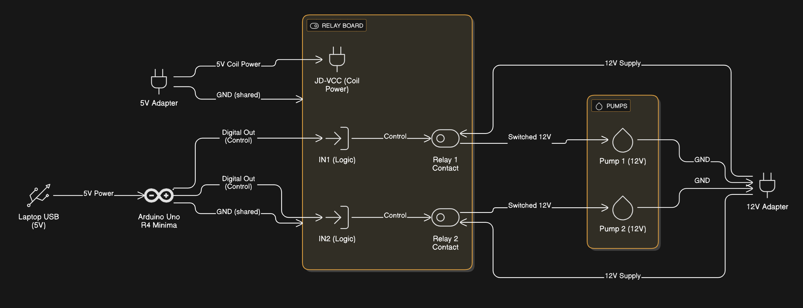
Click the image to view the high-resolution version in a new tab.
Isolation principle:
- The Arduino drives only optocoupler LEDs inside the relay board.
- Coil and motor circuits use their own power adapters.
- Grounds are not shared between logic (Arduino) and motor domains.
Bill of Materials
| Component | Specification | Notes |
|---|---|---|
| Arduino Uno EK | 5 V logic | powered via laptop USB |
| Relay Module | 2-channel, optically isolated, SRD-05VDC-SL-C relays | HL-52S board; JD-VCC jumper removed |
| Peristaltic Pumps | 12 V DC (Kamoer NKP-DC-S10B) | 80 mL / min nominal flow |
| 12 V 2 A DC Adapter | powers pumps | — |
| 5 V 2 A DC Adapter | powers relay coils | isolated coil supply |
| Capacitors | 470 µF / 25 V (×1), 0.1 µF ceramic (×2) | surge & EMI suppression |
| Jumper wires / screw terminals | — | for logic and power routing |
| Multimeter | — | for voltage and continuity checks |
Wiring Guide
Relay Power Connections
| Relay Header | Connect To | Description |
|---|---|---|
| JD-VCC | +5 V from 5 V adapter | coil supply |
| JD-GND | GND from 5 V adapter | coil return |
| VCC | Arduino 5 V | logic reference |
| GND | Arduino GND | logic ground |
| IN1 | Arduino D5 | control Pump 1 relay |
| IN2 | Arduino D6 | control Pump 2 relay |
Ensure the JD-VCC jumper is removed to maintain isolation.
Pump Power via Relays
Each relay block (3 screws): [ NC ] [ COM ] [ NO ]
Refer to Notes for identifying these terminals on the relay.
| Relay | COM | NO | Pump Lead A | Pump Lead B | Function |
|---|---|---|---|---|---|
| Relay 1 | +12 V (from adapter +) | to Pump 1 lead A | — | Pump 1 lead B → adapter − | controls Pump 1 |
| Relay 2 | +12 V (from adapter +) | to Pump 2 lead A | — | Pump 2 lead B → adapter − | controls Pump 2 |
- Jumper COM1 → COM2 to share +12 V.
- Both pumps’ negative wires go to the 12 V adapter’s − terminal.
- NC pins remain unused.
- Pumps are non-polar; swap wires if flow direction is reversed.
Step-by-Step Setup
1️ Relay-Only Test (no pumps)
Upload this simple test sketch to ensure correct alternating logic.
const int relay1 = 5;
const int relay2 = 6;

void setup() {
  pinMode(relay1, OUTPUT);
  pinMode(relay2, OUTPUT);

  // Start OFF (active-HIGH module)
  digitalWrite(relay1, LOW);
  digitalWrite(relay2, LOW);
}

void loop() {
  digitalWrite(relay1, HIGH); // Pump1 ON
  digitalWrite(relay2, LOW);  // Pump2 OFF
  delay(2000);

  digitalWrite(relay1, LOW);  // Pump1 OFF
  digitalWrite(relay2, HIGH); // Pump2 O/"
  delay(2000);
}
Expected:
Relay 1 LED ON → Relay 2 OFF → click alternately every 2 s.
Effect of Relays cycling on the current draw (from a power supply).
2️ Connect Pumps
After confirming relay operation:
- Power off all adapters.
- Wire pumps as per table above.
- Add suppression capacitors.
- Power up in this order:
- 5 V adapter → relay coils
- USB → Arduino
- 12 V adapter → pumps
- Observe alternating pump operation.
Each pump should run for 2 s, then stop as the other begins.
No overlap, no random behavior. If the pumps are turning ON when the relay turns OFF, the board is active- LOW (Refer to Notes)
Troubleshooting
| Symptom | Likely Cause | Solution |
|---|---|---|
| Relay LED blinks, no click | JD-VCC not powered | Check 5 V coil supply |
| Pumps always ON | COM/NO miswired | Move +12 V to COM pins |
| Pumps OFF when LED ON | Board active-HIGH | Use inverted logic (code above) |
| Random triggering / noise | Missing suppression caps | Add 470 µF + 0.1 µF caps |
| Arduino resets | Grounds accidentally tied | Maintain isolation |
| Only one relay works | IN pin miswired | Verify D5 → IN1, D6 → IN2 |
| Pumps OFF when LED ON | Board is active-LOW | See Notes |
📝 Notes and Wiring Checks
To identify the relay terminals, use a multimeter in continuity (beep) mode with the relay unpowered.
The center screw terminal is usually the Common (COM) contact.
When the relay is off, the terminal that shows continuity (beeps) with COM is the Normally Closed (NC) terminal,
and the other one that connects only when the relay energizes is the Normally Open (NO) terminal.Some relay modules are active-LOW, meaning they switch ON when the input pin from Arduino is set to
LOWrather thanHIGH.
This happens because the relay board’s input transistor inverts the logic signal.
If your relay behaves this way, simply invert your control logic in the code — useLOWto turn the relay ON andHIGHto turn it OFF.- Always verify proper power isolation:
- The Arduino 5 V and logic GND should not share a ground with the pump or JD-VCC supply if you’re operating in isolated mode.
- Confirm that JD-VCC jumper is removed for true isolation.
- Before connecting pumps, run the relay-only test to confirm correct switching and alternate LED behavior.
This helps ensure that each relay toggles independently before any 12 V loads are added.
Later versions will include programmable cycle counts and time intervals to fully automate long-term corrosion performance studies.